A taxonomy of physical side channels for AI security and verification
Key Takeaways
- Monitoring or capping a data centre’s network interconnects only protects model weights or verifies training if the operator cannot route enough traffic around the interconnects through physical side channels.
- I derive upper-bounds on channel capacity for 3 channels for a motivated nation-state using the Shannon–Hartley theorem and worst-case physical assumptions, to see if available countermeasures can always constrain these channels below a 10⁵ bit/s per pod threshold.
- None of the 3 can be ignored as low risk without countermeasures.
- Optical is the largest and hardest to manage. Suppression works only when the operator is limited to stock hardware, and every light path/unused optical port is blocked. Additional hidden hardware such as fibre optic cabling could be planted and requires strong monitoring and inspection to detect.
- Power line communication could be above the threshold unless a better filter can be designed.
- Swapping storage drives could be used to communicate above the threshold with today’s countermeasures assuming that monitoring with cameras will not capture every drive. Drive swaps that are missed give a low but not negligible communication rate.
- Measurements of busbar transmission, noise and radiation above 50 MHz, and the drive-movement detection rate in a live facility would clarify the open problems for these side channels. Many of these measurements could be completed in a few days with one rack and commercial analysers.
Detailed Summary
Many proposals for securing AI model weights or verifying compliance with rules on AI may be vulnerable to physical side channels. Proposals often propose tapping or capping the network interconnects inside a data centre, so the operator (the prover) cannot exfiltrate a frontier model, or so they cannot train it without the inspecting party (the verifier) seeing the traffic. That would be defeated if an adversary can covertly route enough traffic around the interconnects through a physical side channel: power lines, emitted light, data storage carried between racks, and others.
In this post, I present an investigation into a subset of known physical side channels, covering how much each channel could carry for a motivated nation-state, and which ones a verifier can rule out, suppress, or detect the use of. While this work targets covert channels used as interconnects, the bounds derived are relevant to security problems including model weight exfiltration.
None of the 3 channels presented here can be ruled out in advance. Optical transmission is the largest and hardest to manage (Figure 1). Power line communication and drive swaps are suppressable in principle, but further work is required to confirm this in practice.
I model a scenario with taps on interconnects between pods of 8 racks. The threshold for concern I set at 10⁵ bit/s, below which one full-parameter gradient synchronisation for a 500B-parameter model (about 0.5 TB per synchronisation) takes > 1 year, completely impractical. Uncompressed exfiltration of model weights would likewise be impractical under this bound. I report results relative to this 10⁵ bit/s threshold alongside a pretraining / RL slowdown factor (against synchronisation once per ~10 s and ~1,000 s respectively). This excludes consideration of decentralised, compressed and low-communication variants of such training.
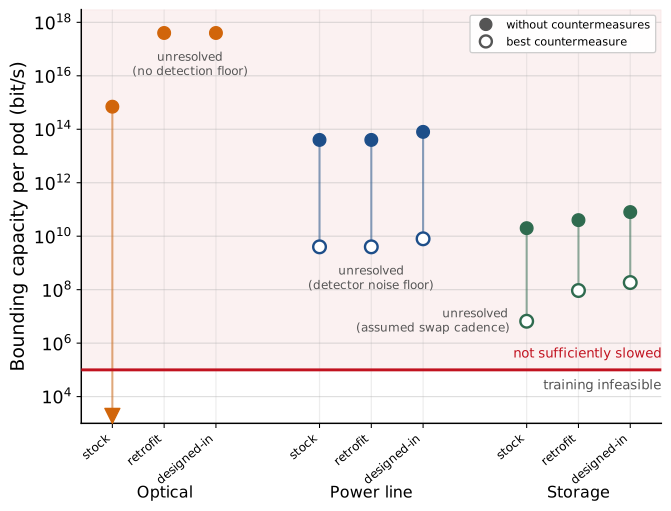
Figure 1: Side channel bounds before and after countermeasures are applied. In the stock scenario, the operator can control only existing standard hardware. Retrofit and designed-in allow the operator to make minor and complete hardware changes respectively to increase the capacity of covert communication.
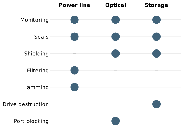
Figure 2: Countermeasures required to minimise each side channel.
Only the optical side channel where the prover has to use stock equipment is sufficiently suppressed by commercially available countermeasures. In other optical scenarios the verifier cannot sufficiently control or detect usable I/O. Power line communication and drive swaps above 10⁵ bit/s could potentially be made detectable with a combination of monitoring, filtering/enclosures and suppression. However, commercial components do not yet achieve this: a 40 dB filter and real-time analyser leave power line signals up to about 4×10⁹ bit/s per pod under the detector noise floor. Reducing this below 10⁵ bit/s needs a custom filter of at least 90 dB. Limiting drive swaps depends on the monitoring miss rate. A better miss rate cannot be assumed without running physical trials.
Important future work is to perform similar analysis for all physical side channels, working towards a sufficient level of countermeasure detail that they can be red-teamed with security experts. This includes additional baseline measurements for data centre busbar noise, transmission and radiation, and both ambient and operational noise levels inside operating data centres for all side channels.
This post does not claim a working demonstration of any adversarial side channel techniques. This is purely a study of capacity bounds, intended to be fully transparent so its assumptions can be scrutinized and debated. A preprint is planned to present a more complete assessment of side channel communication, including countermeasure feasibility.
Previous work: This work builds on earlier analysis of the same problem, in particular Cankaya (2026) on suppressing side channels via retrofitted defences, and differs primarily in deriving bounds from information theory and physics rather than extrapolating from demonstrated attack rates.
Defining a taxonomy for side channel risk
Training of larger, unsafe models is a threat that AI verification aims to prevent. An agreement with a verification system applied to limit or block pre-training will involve the prover (facility operator, AI company or state) declaring workloads, and the verifier (third party, another state) checking compliance with the agreement, and correctness and completeness of the declarations. Commonly proposed tools that could be deployed to verify declarations include a combination of interconnect limits, network taps (which are proposed to be used in tandem with trusted recomputation to check GPU activity) and memory wipes (to remove intermediate weights and activations and significantly slow any attempted training). Models of verification that use network taps vary in where they suggest taps could be placed. They could be covering data center I/O, between each pod, or even each rack. For the purposes of this post, taps are considered to be placed on the interconnects between pods of 8 racks1, but results can be slightly adjusted to work for different tapping schemes.
1 See Appendix A.
Covert channels may allow a motivated AI company or nation state actor to provide incomplete declarations and direct data around taps and wipes. For network taps and memory wipes to be used for near-complete verification, covert communication capacity must be capped. Covert communication can include steganography and other information hidden in on-network channels, and alternative ways of communicating referred to as “side channels”.
This post focuses on physical side channels, mainly targets covert interconnect channels that may support large-scale training, and does not focus on bounds relevant to other covert workloads such as small fine-tunes or model weight exfiltration. This post also does not fully address the viability of interfacing physical side channel emitters or detectors with existing data centre equipment.
The rest of this post presents a structured way of addressing the risk of side channels out to approximately 2030 using parameters set to the worst physically possible case, or the worst expected case for a motivated nation-state prover (where that makes the threat easier to engage with). This allows us to confidently rule out some side channels while properly flagging others that remain insufficiently mitigated.
Setting a target communication rate bound
The target of this work is covert interconnects that enable large-scale frontier training. Available information indicates that large-scale frontier training currently relies on pretraining and full-parameter reinforcement learning (Llama). Both of these require moving the full gradient vector for every parameter. The goal is to define a rate of communication which would make this extremely impractical, and use that to categorise the risk of side channels.
A 500B model in fp8 has a 500×10⁹ × 1 byte = 0.5 TB full-parameter gradient. Choosing a round 10 KB/s bound means one gradient synchronisation would take just over 1.5 years. This is in comparison to normal pretraining synchronisation, which occurs every 1-10 seconds (Llama, HuggingFace)2. A single synchronisation therefore exceeds the length of the entire training run, which renders large-scale training impractical on useful timescales. Even accounting for algorithmic improvements, this is a conservative number that can be used as a threshold to triage side channels. For the purposes of this post, this threshold will be rounded to 10⁵ bit/s3 and reported alongside a cadence slowdown factor (e.g. 10x) relative to a conservative once per 10 seconds pretraining and 1,000 seconds full-parameter RL sync frequency.
2 0.5 TB = 4×10¹² bit; 10 KB/s = 8×10⁴ bit/s; 0.5 TB / 10 KB/s = 5×10⁷ s = 1.6 years.
This number holds up even if some form of compression is possible. Lin et al. show <1000x compression of gradients is possible (Deep Gradient Compression, 2018). At 1000x, one synchronisation is reduced to just over half a day, so the slowdown is still ~5,000x compared to standard training.
3 Rounding 10 KB/s up to 10⁵ bit/s brings this to 0.5 TB / 10⁵ bit/s = 1.3 years which is still impractical.
These thresholds are for the I/O of each pod. This means we also need to consider if the same side channel would cause problems if running between many pod pairs, and if it is possible to have multiple independent side channels per pod.
Parameter-efficient post-training is out of scope here. If it becomes regularly deployed for frontier training it would cut the data per synchronisation by orders of magnitude, perhaps below that needed for inference. If this progress is made, tap- and wipe-based-verification would need to be reconsidered as a viable model. Low-communication training algorithms such as DiLoCo, which synchronise far less often than once per step, are also out of scope,4 although synchronisation that takes over a year is still prohibitive for LoCo training.
4 They would reduce the slowdown factors below by roughly the reduction in synchronisation frequency.
Calculating upper bounds on side channel capacity
As in Cankaya (2026), I use the Shannon-Hartley Theorem (Shannon 1948), which provides an upper bound on channel capacity
\[C \le B\log_2(1 + S_r/N)\]
Where B is the bandwidth of the channel (Hz)5, Sr is the average received signal power over the bandwidth (W), and N is the average power of the noise and interference over the bandwidth (W). We can make clear assumptions about bounds on B, Sr and N (or the signal-to-noise ratio S/N) to estimate worst-case communication rates.
5 It is important to emphasise that this is a bandwidth, not a specific frequency.
Sr is easier to bound as a fraction of the source power
Sr = η(r)·Ss
where η(r) includes the coupling efficiencies (fraction of power lost in coupling) between source, emission and receiver, and the path loss (the fraction of power lost per unit distance r). Sr and Ss are the received and source powers respectively. I assume η(r) = 1 where I cannot justify a smaller fraction.
For N, I conservatively assume the noise floor is generally Johnson-Nyquist noise, N ≈ kT, which applies when hf ≪ kT where h is the Planck constant, f frequency, k the Boltzmann constant, and T temperature. For kT ≪ hf, I assume a quantum limit noise of N ≈ hf (based on Nyquist 1928 and Caves 1982).6
6 At T = 300 K (kT = 4.14×10⁻²¹ W/Hz), the threshold where kT ≈ hf is at f ≈ 6 THz.
When considering additional noise we can scale by a noise factor F, leaving (in the Johnson-Nyquist case)
N = FkTB
Therefore, in the Johnson-Nyquist case we have an overall expression
\[C \le B\log_2\!\left(1 + \eta(r)\,S_s / FkTB\right)\]
This equation gives a basis from which to consider theoretical upper bound bandwidths for different physical channels, and consider the effect of various countermeasures on B, η(r), Ss, and F.
Finally, sometimes it is worth seeing how small the drive signal needs to be to exceed the bound I defined above. In the limit of small signal-to-noise ratio, the above equation is approximated by
\[S_s = FkT\ln(2)\,C / \eta(r)\]
The taxonomy
Before going through example side channels, I want to define terms I will use to categorise side channels.
| State of prover’s communication | Reason | Countermeasure(s) | What would invalidate this conclusion |
|---|---|---|---|
| Infeasible | Physics, extreme expense or extremely dangerous use caps the channel capacity to < 10⁵ bit/s (or equivalent sync frequency for discontinuous channels) | None required | Violating the upper bound on the signal drive |
| Suppressible | A set of engineering countermeasures constrain the channel capacity to < 10⁵ bit/s. | Shielding Filtering Jamming7 |
The countermeasure fails An unmitigated way of using the channel exists |
| Detectable | Covert communication could be > 10⁵ bit/s but can be caught with a set of monitoring measures when above this level. | Channel signal monitoring In-person monitoring Camera-based monitoring |
A different way of using the channel that is undetectable |
| Unresolved | No identified set of countermeasures sufficiently reduce communication to < 10⁵ bit/s. | None sufficient | New countermeasures A tighter bound on some assumptions |
7 Jamming here is assumed to be robust, and not able to be reduced at the prover’s receiver.
These are not necessarily mutually exclusive, but are presented in decreasing order of preference - it is usually preferable to suppress channels to minimise the need to use fallible detection methods.
For each channel, there are also further cases that can be considered based on which approach the prover takes to make use of the covert side channel.
| Category of adversarial tech | I/O | Additional countermeasure |
|---|---|---|
| Stock | Control of existing equipment in a cooperative data centre | Attenuation (shielding, filtering) Channel signal monitoring and anomaly detection |
| Retrofit | Planted or simply retrofitted emitters, carriers and receivers | In-person inspections Technical surveillance counter-measures (e.g. non-linear junction detectors) Camera-based monitoring Teardowns |
| Designed-in | State-of-the-art emitters, carriers and receivers built into a data centre | Supply chain monitoring Design review Construction monitoring |
Three side channels
Power line communication
Carrier
Voltage oscillations carried on power conductors (which may be carrying AC or DC power).
Existing literature
Guri et al. 2018 demonstrated covert communication around 1,000 bit/s.
Avram & Vasiu 2023 demonstrated 130 dB passive power line filtering, but not for data centre equipment
IEEE 1901 standard for power line communication for broadband internet at 5×10⁸ bit/s.
Hasırcı et al. 2017 measured busbar transmission from 1 to 50 MHz with a vector network analyser and found low loss. A 2018 follow-up extended this work over 630–2000 A. No literature was found for above 50 MHz, or for energised, loaded or jointed sections.
Adversarial cases
| Case | Bounding capacity per pod | Prover communication | Additional countermeasures |
|---|---|---|---|
| Stock (prover uses existing power hardware) | < 4×10¹³ bit/s (without countermeasures) < 4×10⁹ bit/s (with countermeasures) |
Unresolved Slowdowns: Pretraining ~100x, RL ~1x |
Commercial real-time frequency analyser Commercial power line filter |
| Retrofit (prover can retrofit better power cables) | < 4×10⁹ bit/s | Unresolved Slowdowns: Pretraining ~100x, RL ~1x |
Real-time frequency analyser (Custom 90 dB) power line filter (Verifier-controlled noise injection) Camera monitoring Tamper evident locks, labels and seals In-person inspections Component review and teardowns |
| Designed-in (prover can design busbar and power lines for optimal covert communication) | < 8×10⁹ bit/s | Unresolved Slowdowns: Pretraining ~50x, RL <1x |
Real-time frequency analyser Power line filter Resistive cladding Camera monitoring Tamper evident locks, labels and seals In-person inspections Component review and teardowns Design review |
Stock:
Starting with C ≤ B log₂(1 + Ss/kTB), the term Ss/kTB will be small8 for C = 10⁵ bit/s (at our threshold) and large B (over 1 MHz wide). Solving for Ss I get that the minimum source signal needed to reach 10⁵ is approximately 3×10⁻¹⁶ W = 0.3 fW, negligibly small. At a drive using all 5 MW of a rack9 and the full 100 GHz bandwidth10 I have a capacity bound of11 < 4×10¹³ bit/s per pod (and only 11% less with the ~130 kW power of current NVL72 racks).
8 Assumption: A thermal noise floor with F = 1.
9 Assumption: Main current carrying infrastructure at the sub-pod level will be the rack input (800 VDC NVIDIA) and busbar (Semianalysis) which will stay below 1,000 V in the near-term (5,000 A at 5 MW per rack).
10 Assumption: Maximum frequency usable by the prover is less than 100 GHz (3 orders of magnitude higher than the IEEE 1901 broadband over powerline standard).
11 Assumption: Any power lines are low-loss, with near-zero losses over distances of a few metres and near-perfect coupling, meaning η(r) = 1 (skin effect calculations, Hasirci 2018).
12 Assumption: Power line filters of approximately 40 dB attenuation (extrapolating Avram & Vasiu 2023) are available (assumed to be for all frequencies above 10 kHz based on extrapolation of MPE).
13 Assumption: Spectrum analysers can reliably detect signals above 1.5x the analyser noise floor.
While they aren’t sufficient independently, the combination of power line filtering and a real-time spectrum analyser12 can help attenuate and then detect covert communication. Assuming the prover knows these are in place, they would likely spread their communication across different frequencies to minimise their detectability. Labelling the noise the prover (verifier) sees Na (Nv) and A the filter attenuation in dB, and using the 1.5x detection floor13, the prover will stay hidden for capacity
\[C < B\log_2\!\left(1 + (1.5\,N_v/N_a)\cdot 10^{-A/10}\right)\]
Where ambient noise dominates, both the prover and verifier will see the same noise and so Nv/Na = 1. This gives a capacity bound \(C < B\log_2(1 + 1.5\cdot 10^{-A/10})\). We now get different results depending on the range in which the prover can practically communicate. Without measuring the ambient noise, I assume that ambient noise dominates in the normally used range < 30 MHz, and above this range thermal noise floor holds for the prover and the analyser noise for the verifier14, with Nv/Na ≈ 24.
14 Assumption: Spectrum analysers have a noise floor of approximately 10⁻¹⁹ W/Hz (e.g. from Rohde & Schwarz).
15 Assumption: The path between pods is a rack input (at least 2 m long), and a bus bar at each pod (at least 50 cm long) totalling 3 m.
A prover can hide more easily by operating below 30 MHz, giving up most of their bandwidth. This is because a 3 m conductor starts radiating above 30 MHz15, reducing efficiency and creating a second detectable signal (see regulated limits). Operating below 30 MHz, the prover has to lower power such that the capacity will be < 5×10⁴ bit/s per pod to avoid detection.
Without being confident about such frequency limitations, I assume that the prover is using the full range up to 100 GHz. Most of this band is not normally used, and absent other information I assume it has noise at the thermal floor. This gives < 4×10⁹ bit/s per pod. While this is expected to emit EM radiation, the signal drive is much lower than the noise floor of commercial analysers (e.g. Rohde & Schwarz) and would be difficult to detect with naive techniques.
Cyclostationary feature detection could extract signals in some of these cases, but likely not enough for wide communication bandwidths with low signal drive. Measuring the power-line and analyser noise in a data centre would define the real threshold of detectability.
Retrofit:
To improve their communication capacity, the prover may try to retrofit better power lines that have a much lower noise floor. However, this type of significant equipment exchange is easy to identify - to assess the noise level and therefore its likely purpose, component review and teardowns can be used.
Similarly, the prover could retrofit couplers or receivers ahead of the power line filters, avoiding attenuation entirely. A mix of camera monitoring, tamper evident labels and seals, and in-person inspections will add to the assurance provided by component review and teardowns here.
Overall, with these measures, I assume a similar upper bound to communication for the prover as the stock case.
Designed-in:
Here we can expect the prover to have designed the facility to maximise covert communication.
Returning to our scenarios above, a bounding assumption is now back to being the thermal noise floor16. For the < 30 MHz power line communication, this means the noise is much less than the sensitivity of the verifier’s analyser. However, the result here is only slightly better for the prover - to avoid detection, they can have a slightly higher capacity at approximately 10⁶ bit/s per pod.
16 Assumption: Prover can design power lines that operate at near thermal noise floor.
17 Assumption: Prover can custom design busbar and rack inputs to increase frequency ceiling, which is generously assumed to be < 200 GHz.
18 Assumption: Prover can design busbar and rack inputs to minimise radiated signal.
Operating at 200 GHz17 with no detectable radiated signal18, the prover can now reach 8×10⁹ bit/s per pod accounting for 40 dB of filtering. To reduce this to below 10⁵ bit/s, we need a custom designed 90 dB filter, which would reduce the capacity to 8×10⁴ bit/s. If a 90 dB filter is impractical, we could also investigate mandating resistive coatings to increase losses at high frequencies when the signal travels in the conductor’s skin.
Overall result
This side channel is unresolved, despite having countermeasures available that reduce maximum capacity. The biggest constraint and uncertainty on the risk this channel poses is how much of the spectrum a busbar and input cable actually carries, and what their losses are. If the usable band stops soon after 50 MHz, commercial countermeasures make the channel unusable. If not, frequencies extend quite high and currently available countermeasures don’t appear robust enough.
The best countermeasure for this side channel is a better filter. Designing a per-rack filter of at least 90 dB would ensure signals as estimated here would be below 10⁵ bit/s/pod for frequencies up to 200 GHz. Avram & Vasiu demonstrated 130 dB but only for 30 A and 9-500 kHz, so it is unclear if 90 dB on a busbar in MHz or GHz range is achievable.
While viability is unclear, verifier-controlled noise injection where the verifier can subtract the noise from analyser measurements would raise the prover’s noise floor and reduce the attenuation needed.
Electromagnetic radiation (6 THz - 1.5 PHz)
Carrier
Radiated near-infrared, optical and ultraviolet light between 6 THz and 1.5 PHz. This is treated as a range because it is bounded below by the frequency at which photon shot noise overtakes thermal noise, and above by where air stops transmitting electromagnetic radiation.
Existing literature
Free-space optical communication experiments show communication rates of ~10¹¹ bit/s range (Guan et. al 2025).
UVC micro-LED at milliwatt output demonstrated at 8×10⁸ bit/s over 3m (Zhu et. al 2021)
LED-it-GO (Guri et al 2017) demonstrated a status-LED covert optical channel at 4×10³ bit/s.
Dahan & Mahlab (2017) show OTDR trace comparison catches commercial clip-on optical taps but nation-state-level taps make OTDR detection near-impossible.
Adversarial cases
| Case | Bounding capacity per pod | Prover communication | Additional countermeasures |
|---|---|---|---|
| Stock (prover uses existing hardware to emit) | < 7×10¹⁴ bit/s (without countermeasures) < 5×10⁹ bit/s (with enclosures) / ~0 bit/s (with complete port blocking) | Suppressible (conditional on completeness) Slowdowns: Pretraining >170x, RL only >1x (with enclosures) / Fully slowed (with complete port blocking) |
Tamper-evident port blockers Sealable rack enclosures with baffled ports Photodiodes inside enclosures |
| Retrofit (prover retrofits emitters and plants reflectors) | < 4×10¹⁷ bit/s | Unresolved Slowdowns: N/A |
Tamper-evident port blockers Sealable rack enclosures Photodiodes inside enclosures In-person inspections Tamper-evident seals Component review and teardowns |
| Designed-in (prover designs the optimal facility with emitters, reflectors and detectors) | < 4×10¹⁷ bit/s | Unresolved Slowdowns: N/A |
Tamper-evident port blockers Sealable rack enclosures Photodiodes inside enclosures In-person inspections Tamper-evident seals Component review and teardowns Design review |
Stock:
To reach C = 10⁵ bit/s, the prover needs approximately 0.3 fW at 6 THz, 30 fW for visible frequencies (600 THz) and 70 fW at the top of the band (1.5 PHz)19. Once again, the drive power is not the limiting factor.
19 Assumption: Above 1.5 PHz air starts absorbing emitted EM radiation.
20 See Appendix A.
21 Assumption: Assume optical coupling and path loss in usual cases is near-lossless with η(r)=1 over a few metres.
Bandwidth cannot exceed the maximum frequency, so setting B = f and using the rack drive of 5 MW20, I get maximum capacities21 of 3×10¹⁴ bit/s/rack at 6 THz, 2×10¹⁶ bit/s/rack at 600 THz, and 5×10¹⁶ bit/s/rack at 1.5 PHz as theoretical upper bounds. The maximum frequency is therefore also not the limiting factor. For non-collimated light divergence falls as 1/f, so the fraction a fixed receiver captures rises as f², while the noise floor hf rises only as f. Higher frequencies are therefore slightly better for the prover, but it is only logarithmically different.
The fastest source already wired to the data path are optical transceivers22 without fibres connected23, which could be overridden in firmware to emit. These devices are uncollimated without the fibre present, and diverge with half angle θ = c / (f·π·w₀) where c is the speed of light and w₀ is the beam waist radius (the narrowest radius of the beam).
22 Assumption: An average of 1 optical transceiver is available to use at all times per rack.
23 Assumption: In a stock facility fibre-optic links are tapped and therefore don’t need to be considered.
24 Assumption: Optical transceivers have a per lane symbol rate bounded by 500 Gbaud and 8 lanes per connector (rounding up from Keysight 2023).
Assuming 8×500 Gbaud24, the bandwidth from the idealised Nyquist frequency gives B = 2×10¹² Hz. This passes 10⁵ bit/s at over 9 fW, and for a 5 MW drive gives a capacity bound of < 9×10¹³ bit/s/port.
Since uncollimated light spreads, I calculated the fraction of this emitted signal a receiver collects as a function of the receiver distance and size. A beam leaving a fibre with mode-field radius w₀ diverges with half-angle θ = c/(f·π·w₀), so at distance z the beam a receiver of diameter d captures the proportion η = (f·π·w₀·d/(2c·z))². At 200 THz, w₀ = 5 µm and a distance of 2m25, θ = 5.5°. A 10 mm receiver cuts maximum power to Ss×6.9×10⁻⁴, but only drops the maximum capacity to 7×10¹³ bit/s. Even at normal operating power of 10 mW, the receiver can be down to a size close to the wavelength and still reach 10⁵ bit/s.
25 Assumption: A representative set of parameters for an optical transceiver is a 200 THz carrier frequency, 10 mW drive and a beam waist radius of approximately 5 µm (RP Photonics, Corning).
This presumes that the transceiver aperture is facing another pod, which may not be the case. However, even indirect transmission isn’t sufficiently attenuated.
First, I consider diffuse reflection. This is an approximation of the signal reflecting off walls, ceilings, and other matte surfaces26. The fraction of an emitted signal received by an area Ar is
26 Assumption: Data centre interiors are matte finish.
\[\eta = \rho\,A_r / (\pi r^2)\] (derived from Lambertian properties in Palmer & Grant 2010)
where ρ is the surface reflectance (here assumed to be a perfect ρ = 1), and r is the distance from the reflection point to the receiver (University of Tennessee). This diffuse reflection is not directed, so anything in line of sight of the reflection point will receive the light. Assuming the light travels 5 m to the edge of the facility27, is reflected, and travels 5 m to another pod, there it will spread to 0.95 m in diameter over the first 5 m and the diffuse reflection over 5 m gives 60 dB loss. At a 10 mW source I get 10¹¹ bit/s per port, which needs three bounces to fall below 10⁵ bit/s, and four bounces at a 5 MW drive. I cannot assume that there are at least this many.
27 See Appendix A.
Second, I consider specular reflection, off metals such as aluminium and other gloss surfaces such as glass and polished floors. Over the same 10 m path the beam is 1.9 m in diameter, and aluminium reflects about 98% at these wavelengths (refractiveindex.io) - effectively lossless.
The easiest and most robust way to stop communication is to remove or cover all known sources of emission in these wavelengths. Optical ports can have tamper-evident port blockers placed in them (SmartKeeper, PadJack), and lower capacity status LEDs can be covered by tamper-indicating labels (NIST).
A more operationally disruptive and less reliable approach is to use sealable rack enclosures. Any opaque material such as metal will sufficiently block all wavelengths in this band. Mandating baffled vents (Fest 2013) will help increase the number of diffuse reflections needed if there is a portal through which they can propagate. Rack enclosures are not perfect - when enclosures are open, the channel can be used to communicate gradients. The capacity can be estimated by the fraction of time the enclosure is open. For example, a believable need to open racks for 1 hour per week for maintenance means racks are open for 0.6% of the time, which results in a slowdown of only at least 170x on pretraining assuming lossless transmission. Photodiodes inside the enclosure would detect opening or emission, and could be used to flag suspiciously long or regular openings.
Finally, if there are operation reasons that ports need to be left unsealed, we can enforce dark, matte finishes on as much of the interior of the data centre as possible. This will at least minimise the specular reflection, meaning any indirect communication would be via the lossier diffuse reflection. Minimising the use of translucent panels and putting additional row barriers up or changing the data centre layout to minimise line of sight would also help.
In all these approaches, it is important that the blocking covers every port or path. Since this channel is so high capacity, even having the pods connected by line of sight or reflections through other pods would still likely support covert training. Ensuring blocking is complete requires in-person inspection of ventilation and cooling penetrations, cable entries, doors and windows.
Retrofit:
At any frequency, emitters will be chosen to be at the top of the band28 in question, with B = f giving C = 5×10¹⁶ bit/s.
28 Assumption: Planted emitters can use the full 5 MW rack drive, any frequency in the band, and a collimating lens.
The prover can use collimating lenses with small openings in enclosures to render the enclosures useless for blocking signal receipt. Having a collimating lens replaces the beam waist w₀ in θ = c/(f·π·w₀) with the radius of the lens, so a 5 mm lens makes a beam 0.76 mm wide at a distance of 2 m (compared to 0.4 m in the stock case). This means a 1 mm gap at 2 m can carry the entire signal, and in practice any size hole can carry above 10⁵ bit/s.
The prover can also plant reflectors in strategic locations around the data centre. This means emitted signals can be near-perfectly reflected to the right location, even where it requires several steps, and can be used in tandem with the small gaps and planted receivers, which also give the prover more options for where to place their communication equipment.
Finally, the prover may just decide to plant some fibre optic cable29 to carry the signal most or all of the distance it needs, and therefore avoid countermeasures including rack enclosures. If fibre is added to the main line, baselining every declared fibre with an optical time-domain reflectometer catches a tap or splice added to a monitored line, by comparing against a reference (VIAVI ONMSI). A capable prover could use low-loss taps which make detection difficult (Dahan & Mahlab 2017). Physical inspection is still required to catch this and completely separate fibre channels.
29 Assumption: Planted fibre is not a tapped link, so it is in scope.
Countermeasures, in addition to those for the stock case, are primarily detection-based. Verifiers should inspect enclosures and cables against reference designs, use tamper-evident seals on cable routes and trays, in-person inspection for planted reflectors and reflective surfaces, and teardowns to catch retrofitted tools.
Designed-in:
A designed facility can widen outlets30, build reflective interiors and add steering mirrors (MEMS) to dynamically change reflection strategies31. They can also lay fibre optics in alternative places during construction, either as full substitutes for the main interconnects, or to partially carry this channel to a coupled channel or better location. Design review, supply chain monitoring and construction monitoring could limit these.
30 Assumption: Emitter aperture, outlet geometry, interior finish and layout are all design choices.
31 Assumption: Many emitters can be designed in across the band, each independently modulated.
Overall result
This side channel is unresolved, and it is the highest-capacity and easiest to use channel in this post. To mitigate this channel we need to block unused optical ports, paint interiors with a dark matte finish, and seal enclosures with baffled vents.
Planted fibre is not addressed by any optical countermeasure and relies on the same monitoring measures as covert storage. That is the part most in need of work.
I place low confidence on the accuracy of countermeasure figures here. Measuring the rate of detection and false negatives for real data centres and these inspection targets is the only way to be confident that they are sufficient.
Storage & memory swaps
Carrier
Humans or equipment physically move solid state or flash storage between pods32.
32 Assumption: Choose to use SSD hot swaps because CPU memory requires cooling, GPU memory is soldered, and both could be subject to wipes.
Existing literature
No published covert channel demonstration.
Adversarial cases and countermeasures
| Case | Bounding capacity per pod33 | Prover communication | Additional countermeasures |
|---|---|---|---|
| Stock (prover uses existing SSDs and interfaces, simple verification) | 2×10¹⁰ bit/s (no countermeasures) Syncs at most every 3 minutes < 8×10⁷ bit/s (with countermeasures) Syncs < every 15h |
Unresolved Slowdowns: Pretraining >5,000x, RL >50x |
Records checks Camera monitoring |
| Stock (prover uses existing SSDs and interfaces, more advanced verification) | < 7×10⁶ bit/s Syncs at most every week |
Unresolved Slowdowns: Pretraining > 60,000x, RL > 600x |
Camera monitoring Drive telemetry On-site drive destruction (Verifier-controlled drive storage) |
| Retrofit (prover uses covert storage interfaces in SSDs or RAM modules) | < 10⁸ bit/s Swaps at most every 12h |
Unresolved Slowdowns: Pretraining > 4,000x, RL > 40x |
Camera monitoring Tamper evident locks, labels and seals In-person inspections (Sealable rack enclosures) (Component review and teardowns) |
| Designed-in (prover uses covert storage in many locations) | < 2×10⁸ bit/s Swaps at most every 6h |
Unresolved Slowdowns: Pretraining > 2,000x, RL > 20x |
Camera monitoring Tamper evident locks, labels and seals In-person inspections Sealable rack enclosures Component review and teardowns Design review |
33 Since drive swaps are discrete, the bitrate is an effective rate of (drive size ÷ swap interval).
Stock:
With these assumptions, the prover has an upper bound rate34 using stock components of35 < 2×10¹⁰ bit/s without countermeasures. A prover only needs to do a drive swap every 4×10⁷ seconds, or every 1.3 years, to reach an effective 10⁵ bit/s communication rate. With 400 normal drive replacements36 per year per pod37, this means they can use normal drive swaps to do it38, and they do not have to use unused empty slots (GB200 service manual).
34 Assumption: While SSDs have up to 10 TB drive size, only 0.5 TB = 4×10¹² bit SSDs are necessary for gradients and these will be used.
35 Assumption: Swapping drives every 200 seconds on average per pod is possible with OC5 resourcing.
36 See Appendix A.
37 Assumption: Data centres have at most a 5% annual replacement rate (Backblaze).
38 Assumption: Drives instantaneously start writing the next set of gradient data upon drive swap. With a write speed of at most 20 GB/s, this takes ~25 seconds to write. Write speeds of ~15 GB/s are currently commercial (Samsung 9100 Pro).
39 Assumption: Simple monitoring (camera-based) can catch a replacement rate 1.5x the normal rate.
Catching a replacement rate of 1.5x the normal rate39 would limit the prover to < 8×10⁷ bit/s per pod on average, and slow pretraining by over 5,000x compared to normal (50x for RL). This monitoring is possible by defining a base drive replacement rate from manufacturer or cooperative data centre records, having data centres declare drive locations, and using camera-based monitoring in all rack drive areas to verify this.
A more robust solution is to prevent drives from moving from one pod to another. This can be done by having a record of drive insertions and removals, a way to verify this record, and having drives destroyed immediately after removal. The record could use Redfish events, the verification being camera-based monitoring or random inspections, and drive destruction following the NIST standard procedure for media sanitisation. Verifier-controlled drive storage areas could allow for destruction batching. The error rate of the monitoring would define how low the covert communication rate could be driven (and conversely how high the rate of detection of covert communication would be). This value is difficult to estimate. I will assume it is a fraction of the frequency of normal drive replacements, and therefore less than once per week. This is still far from the reduction down to once per 1.3 years needed to get below 10⁵ bit/s effective capacity.
Retrofit:
At the upper bound of micro-SD storage density40, 0.5 TB could be stored on approximately 40 mm3 of memory, less than 2 grains of rice in volume. At once per 100 seconds41, absent verifier detection42, this gives an average rate of 4×10¹⁰ bit/s and a 10x slowdown on pretraining.
40 Assumption: Micro-SD memory density will be less than 10¹¹ bit/mm³ by 2030 (36kr).
41 Assumption: Hidden memory can be designed such that swapping hidden storage once every 100 seconds per pod on average is possible with OC5 resourcing.
42 Assumption: Frequency of swaps are limited by this timing rather than read/write speeds.
43 Assumption: Such devices are not feasibly detectable by body or delivery scanning.
44 Assumption: Maintenance staff do daily inspections, but sustained inspections above twice daily across all pods are detectable and suspicious.
Given the size of the memory, there are many ways it could be interfaced if unobserved43. For example, the prover could hide insertions and removals within normal maintenance activities44. In this scenario, avoiding detection and using 0.5 TB storage gives an average bandwidth of 10⁸ bit/s and slows sync frequency by over 4,000x compared to normal (40x for RL).
This could be further slowed by widely using tamper-evident devices. In the short term, existing tamper-evident locks and labels (e.g. following NIST FIPS 140 standard) can be used to cover all ports (locks for unused, labels for in-use or infrequently used ports). A sample of these can be checked during inspections, providing evidence of their use which can be investigated. In the medium term, verifiers can adapt transmitting, resealable seals (e.g. IAEA EOSS) to as many port types as possible, allowing camera footage to be matched with unsealing events. Maintaining use of rack enclosures would reduce the number of seals needed.
To cover the potential for retrofitting storage or ports in replacement parts during the data centre’s lifetime, reviews of components against reference designs and potential teardowns may be required.
Designed-in:
A facility designed for this faces the same problems as the retrofit case, just larger in scale: there are more ports available45, specifically designed to be fast to use. Estimating the capacity is difficult, but I will assume a 100% improvement over the simple retrofit case in frequency.
45 Assumption: Can design in hidden ports at many locations throughout each pod.
Oversight would require a commensurate scaling up of comparison to reference designs across all facility components, particularly those that interface directly or indirectly with the accelerators. More widespread sealing and tamper-evident labelling, including of cables, would also be desirable. Overall, the verification burden would be very large.
There is no known covert automated method to transfer physical storage media between pods, and so covert swaps will continue to require physical human interaction. Given this, covert sync frequency will still be significantly limited by this cadency, given the listed set of countermeasures. I will assume that built-in infrastructure allows this cadence to be twice as frequent as for retrofitted infrastructure46. This leaves a 2,000x slowdown for pretraining and a low 20x slowdown for RL.
46 Assumption: These can be designed so that swapping hidden storage once every 100 seconds per pod, on average, is possible with OC5 resourcing.
Overall result
This side channel is very high average capacity, and could be used for large-scale training given maximal resourcing from the prover. Countermeasures including simple monitoring, drive logging and destruction help reduce the cadence, and would also be useful in supporting AI security goals, but do not remove the risk fully. Studying the verifier’s ability to detect drive movement in an active data centre should be studied to provide higher-confidence estimates than those provided here.
Other channels
In the interests of enumerating all the physical side channels I am aware of, and soliciting input on whether I have missed any, I have included summary preliminary results for other physical side channels below.
| Side channel | Preliminary status | Priority countermeasures |
|---|---|---|
| Modulating power consumption | Infeasible | |
| Thermal (rack coolant) | Nearly infeasible | |
| Thermal (solid conduction) | Infeasible | |
| Near-field magnetic | Unresolved | Mu-metal shielding |
| Long wave radio | Detectable | Inspection for large antennas |
| Radio and microwave | Unresolved | TEMPEST-grade enclosures |
| Millimetre-wave and thermal infrared | Unresolved | Minimising duct apertures |
| X-ray and gamma | Infeasible (unsafe) | Standard radiation monitoring |
| Acoustic (through air) | Unresolved | Damping and acoustic detectors |
| Acoustic (through coolant) | Unresolved | Acoustic detectors |
| Acoustic (through solids) | Unresolved | Damping and acoustic detectors |
| Gravitational | Infeasible and detectable | |
| Particle (nucleons, fundamental particles) | Infeasible and/or detectable |
Almost no physical side channel (other than chemical particle communication) can be completely ruled out against a motivated, capable and well-resourced prover. For example, communicating using gravitational field changes is possible in theory, but would require an obvious mass and large detectors which would be captured by basic camera monitoring.
Conclusion and next steps
Across the 3 channels examined in detail, none is closed in every scenario by currently available countermeasures. The power-line channel is slowed but not resolved; resolution depends on several empirical measurements favouring the verifier. The optical channel is minimally slowed, and relies entirely on whether reliable containment of racks is possible. The storage channel is slowed, but not enough to be below 10⁵ bit/s. All detailed channels are mitigated significantly by layers of techniques that raise detectability.
Many assumptions in this post require validation through further work. Some of the most important next steps to resolve open questions identified here include:
| Future work | Outcome | Relevant channel(s) |
|---|---|---|
| Audit existing surfaces in a data centre | Determine if surface finish could be sufficiently controlled to minimise reflected optical communication | Optical |
| Red-teaming of OC5 planted fibre and low-loss taps | Determine if OC5 fibre can be reliably detected when planted on the main optical line | Optical |
| Measure busbar transmission above 50 MHz | Set the usable bandwidth which decides if custom filters are needed | Power line communication |
| Measure busbar noise floor | Confirms noise floor assumptions are correct for prover and verifier calculations | Power line communication |
| Measure radiated signal from a driven busbar as a function of frequency | Identify where radiation starts significantly, and confirm its detectability and usability for EM communication | Power line communication, EM |
| Measure or model filter losses as a function of frequency up to MHz and GHz range | Confirm or refute that high attenuation commercial filters give the same attenuation at unmeasured higher frequencies | Power line communication |
| Theory and modelling to determine feasibility of a 90 dB power line filter | Determine whether attenuation is sufficient to resolve power line communication | Power line communication |
| Empirically demonstrate verifier injection of noise and cancellation on the verifiers own measurements | Decide if filtering plus noise injection is feasible with commercial components | Power line communication |
Many of these could be completed in a few days with a single GPU rack, a few commercial analysers and a computer for data analysis.
Further work is also required to check aspects of feasibility including adaptability to AI data centres, cost, difficulty of installation, obstructiveness to day-to-day operations, and proof of sufficient security.
I welcome any and all feedback on this preliminary work.
Note: This blog post was produced during and enabled by my participation in the MATS 10.0 programme.
Appendix A: Facility scale and conditions
Bounding side channels at the pod level requires defining attributes of the worst-case large AI data centre we may care about. These include the maximum power draw at different levels (for power-based communication), ambient temperature (for sensor performance) and standoffs between different accelerators and nodes (relevant for signals that decay over distance). These assumptions are listed below.
| Parameter | Upper bounding value | Source | Justification |
|---|---|---|---|
| GPU package power | 10 kW | NVL72 1.7 kW NVL576 4.2 kW |
Bounding value assumed. Continued increases limited by cooling. |
| Rack power | 5 MW | Published figures go up to 600 kW | Bounding value assumed several times current maximum, and matches a round 500 GPUs. Limited by cooling. |
| Pod power | 40 MW | SuperPOD scalable unit is 8 racks | As cited. |
| Data centre power | 5 GW | ~1 GW quoted power for largest data centres in development in 2026 (IEA 2025) | Bounding value larger than 2026, but practically cannot get much higher. |
| Pods per data centre | 100 | Derived | Derived from data centre power / pod power, and then rounded down to get a lower bound. |
| Storage drives per rack | 1,000 | Current racks use ~1.25 drives per GPU (NVIDIA DGX H100) | Choosing a generous upper bound based on the 500 GPUs per rack figure above. |
| Storage drives per pod | 8,000 | Number per rack x racks per pod | As derived |
| Removable memory modules per rack | 2,000 | NVIDIA is moving to socketed SOCAMM modules for Vera (SemiAnalysis) | Assuming an upper bound of 4 per GPU x number of GPUs |
| Removable memory modules per pod | 16,000 | Number per rack x racks per pod | As derived |
| Ambient temperature | 300 kelvin (K) | Convention | Assumption for reference values, other temperatures considered case-by-case. |
| Data centre scale | Single hall on the order of ~100m | Estimated | Smaller size assumptions favour covert communication. |
| Scale standoffs | ~1 cm between adjacent GPUs, ~0.5 m between adjacent racks, ~2 m between adjacent pods, ~5 m to the edge of the facility from the nearest pod. | Estimated | Lower bound estimate increases channel capacity. Significantly smaller would be impractical for facility operations. |